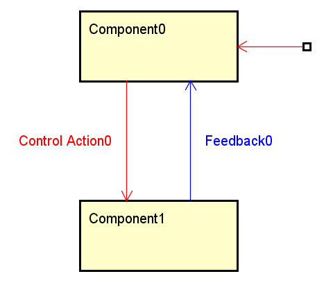
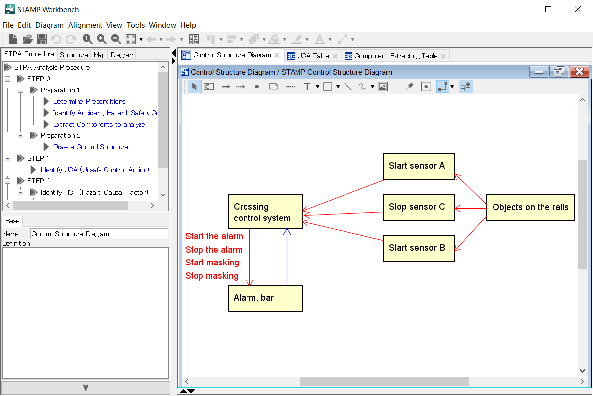
The Control Structure Diagram shows the structure and relationship of the analysis subject.

Description of icons Type Icon Description Select Component Add a component. Link Add a link. Feedback link Add a feedback link. Endpoint Add a start/end point. For others, refer to Common Diagram Elements.
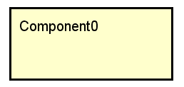
Click on the[Component] button on the tool bar, and click on the diagram. Or double-click on the Control Structure Diagram to create a component.
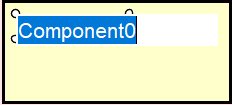
Double-click on the Name of the Diagram Element in the Diagram Editor to edit the name.
Or edit under the Base tab of the Component property.
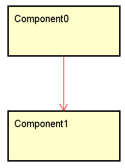
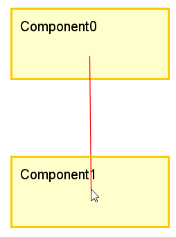
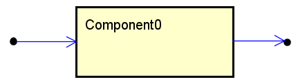
Click on the  [Link] button on the tool bar and select the source and target components that are to be connected to the link.

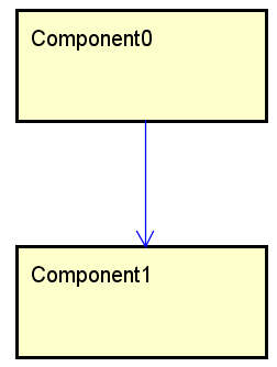
After creating a link
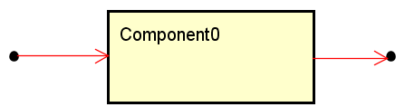
The link can be created between the start/end point and component.
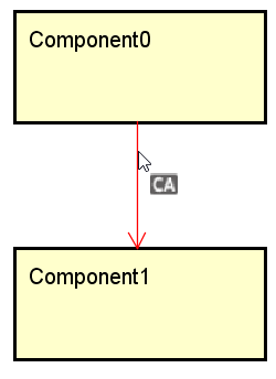
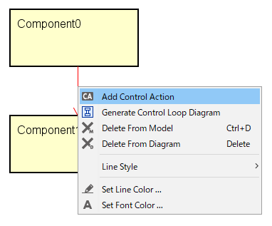
Hovering the mouse over the link will display the  [Control Action] icon. Click on the icon to create a control action.
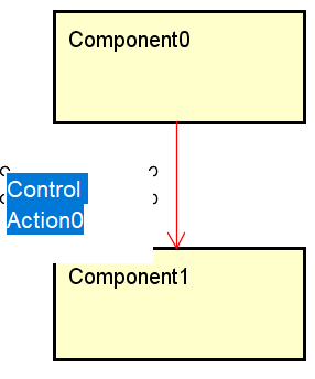
After creating a Control Action
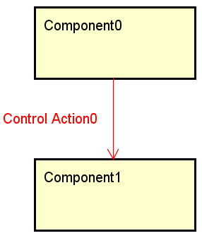
Click on [Add Control Action] on the context menu.
Double-click on the control action of the Diagram Editor and edit it.
Or edit under the Base tab of the Control Action property.
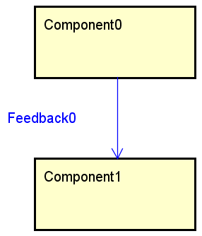
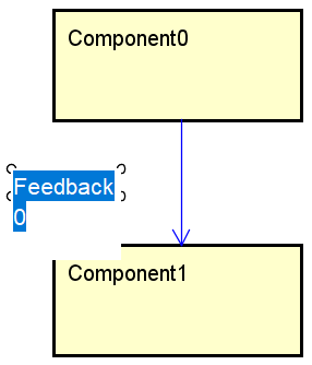
Click on the
[Feedback Link] button on the tool bar, and select the source and target components that are to be connected to the link.
After creating a feedback link
The feedback link can be created between the start/end point and component.
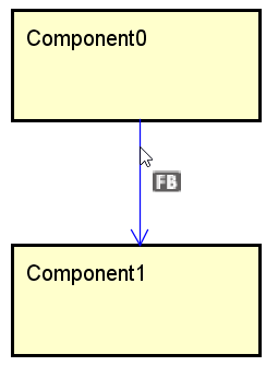
When the mouse hovers over the feedback link, the
[Feedback] icon is displayed. Click on the icon to create the feedback.
After creating a feedback
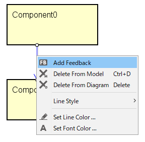
Click on [Add Feedback] on the context menu of the feedback link.
Double-click on the Feedback in the Diagram Editor to edit it.
Or edit under the Base tab of the Feedback property.
Click on the
[Endpoint] button on the tool bar then click on the diagram.
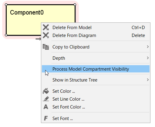
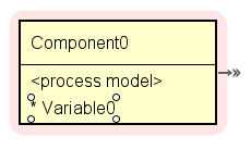
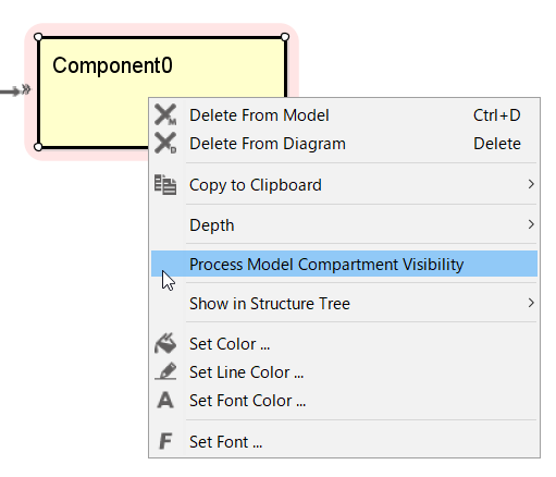
Click on [Process Model Compartment Visibility] on the context menu of the component.
Process Model, Process Variable, Process Value can be added under the Process Model tab of the component. For adding, refer to [Process Model] tab.
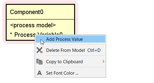
Click on [Add Process Variable] on the context menu of the component.
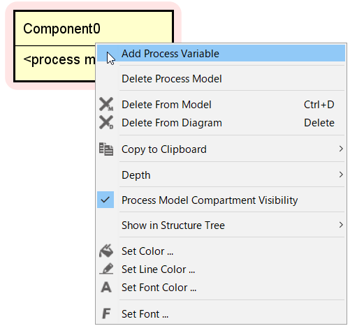
Select the Process Model Variable and add with the Enter key.
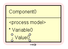
Click on [Add Process Variable] in the context menu of the Process Model Variable. The context menu of the Process Model Variable is displayed by right-clicking on the Process Variable in the Diagram Editor.
Select the Process Model Value and add with the Enter key.
Double-click on the Process Variable and Process Value of the component in the Diagram Editor to edit them.
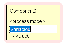
To change the order of the Process Variables and Process Value, move them by dragging and dropping on the diagram.
Change the Process Model Compartment Visibility/Non-visibility of the component, using [Process Compartment Visibility] on the context menu of the component.
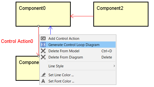
Click on [Generate Control Loop Diagram] in the context menu of the Link.
Click on [Generate Control Loop Diagram] on the context menu of the control action.
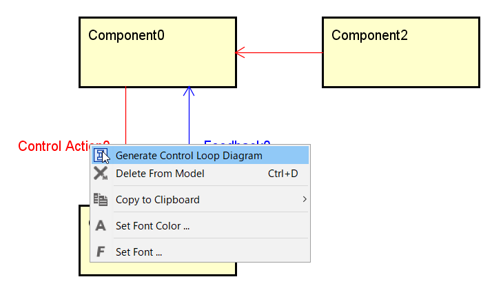
The Control Loop Diagram is generated by extracting the components directly related to the selected link or control action.
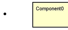
Any component that is not directly connected to the control action is displayed as an omission (square).
The start/end points are displayed as they are.