Innovation Platform Agency, Japan
Component
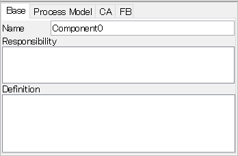
[Base] tab
- Name
- Responsibility
- Input the responsibility of the component.
- Definition
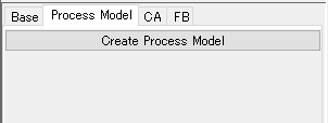
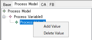
[Process Model] tab
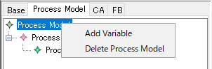
Process Model
- [Add Variable]
- Add a Process Variable to the Process Model.
- [Delete Process Model]
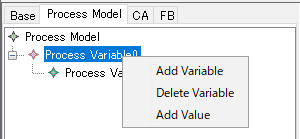
Process Variable
- [Add Variable]
- Add a variable to the Process Model.
- [Delete Variable]
- Delete a Process Variable.
- [Add Value]
Process Value
- [Add Value]
- Add a value to the Process Value.
- [Delete Value]
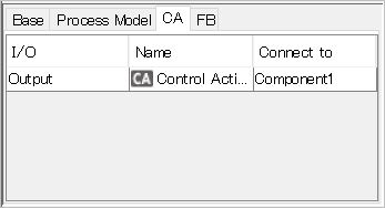
[CA] tab
- I/O
- Display the I/O of the control action.
- Name
- Display the control action of the link connected to the component.
- Connect to
- Display the component connected to the link.
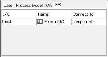
[FB] tab
- I/O
- Display the I/O of the feedback.
- Name
- Display the feedback of the feedback link connected to the component.
- Connect to
- Display the component connected to the feedback link.