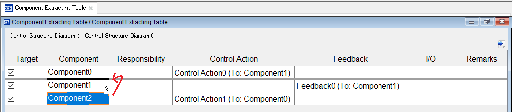
The Component Extracting Table is a table to create a control structure for representing the relations among components of the analysis subject. The Component Extracting Table is created under the project.
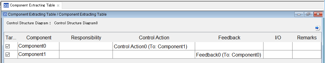
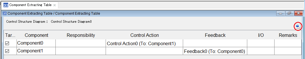
In [Control Structure Diagram] at top left on the Component Extracting Table, the name of the synchronized Control Structure Diagram is displayed.
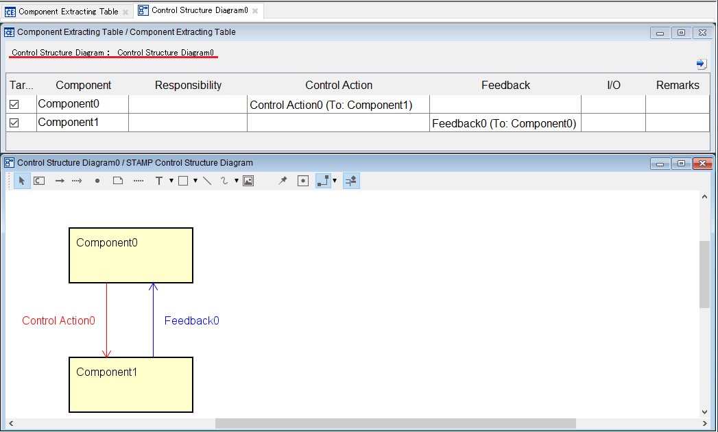
Adding, deleting, and editing the targets/components/control actions/feedback/Inputs and outputs of the Component Extracting Table will be reflected in the synchronized Control Structure Diagram.
The Control Structure Diagram will be synchronized with the operations below.
When [Target] is set to ON, the component is the analysis subject.
When the Target is changed from OFF to ON, the Diagram Element of the component will be added in the synchronized Control Structure Diagram if it does not exist in the diagram.
When [Target] is set to OFF, the component is excluded from the analysis subject.
When the Target is changed from ON to OFF, the Diagram Element of the component will be deleted from the synchronized Control Structure Diagram if it exists in the diagram.
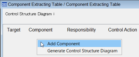
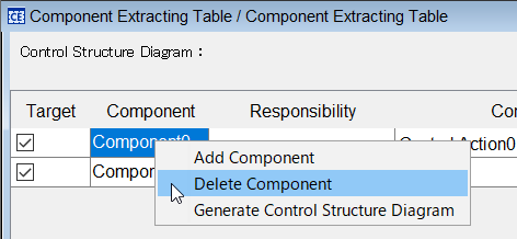
Right-click on a blank column or row in the Component Extracting Table and click on [Add Component] on the context menu.
Double-click on the cell of a component to edit the component.
Right-click on a row of the Component Extracting Table and click on [Delete Component] in the context menu.
Double-click on the cell of a responsibility to edit the responsibility. Multiline input is enabled in the Responsibility columns.
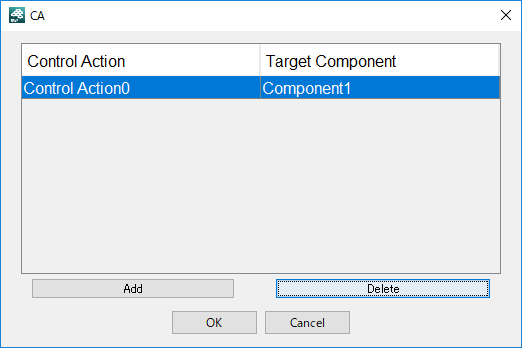
Double-click on the cell of a control action of the Component Extracting Table to display the CA dialog.
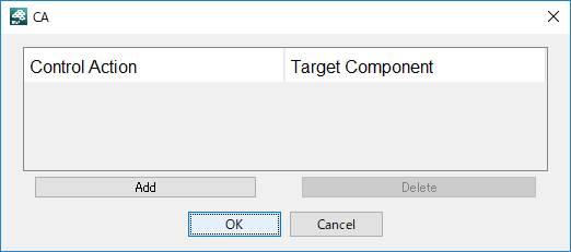
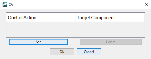
Click on the [Add] button on the CA dialog to display the Target Component dialog.
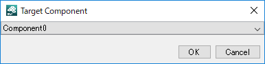
Select a component to be specified as a target from the drop-down list in the Target Component dialog. Then click on [OK] to add a control action.
To edit the control action, double-click on the cell of a control action to edit it.
Double-click on the cell of a control action of the Component Extracting Table to display the CA dialog.
Select a control action in the CA dialog, and click on the [Delete] button.
This operation does not delete the link.
Double-click on a cell of the feedback in the Component Extracting Table, to display the FB dialog.
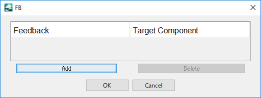
Click on the [Add] button in the FB dialog to display the Target Component dialog.

Select a component specified as a target from the drop-down list in the Target Component dialog. Then click on [OK] to add a feedback.
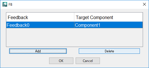
To edit the feedback, double-click on the cell of a feedback to edit it.
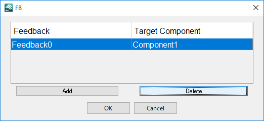
Double-click on a cell of the feedback in the Component Extracting Table, to display the FB dialog.
Select a feedback on the FB dialog, and click on the [Delete] button.
This operation does not delete the feedback link.
Double-click on a cell of the input/output in the Component Extracting Table to display the I/O dialog.
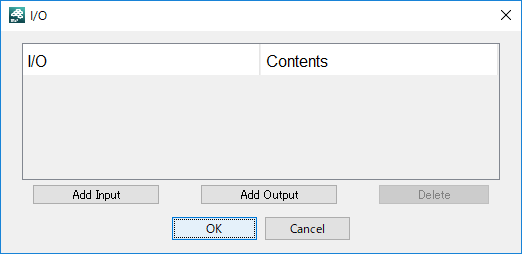
To add a control action of input to a component, click on the [Add Input] button.
To add a control action of output to a component, click on the [Add Output] button.
The control action of the added Input / Output can be edited by double-clicking on the Contents cell.
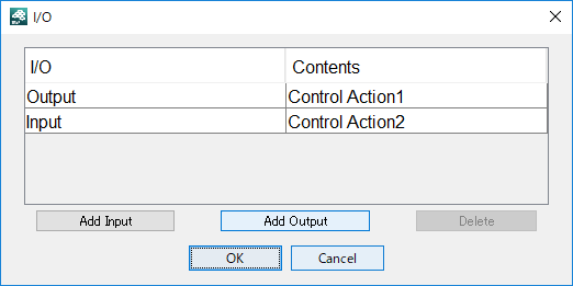
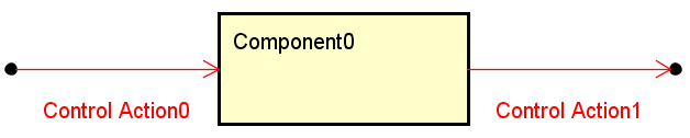
If an input is added to the Component Extracting Table with the synchronized Control Structure Diagram, the start point, link and control action are added in the diagram. As an output, the link, end point and control action are added.
If the component has start and end points and a link, the control action is added to the link.
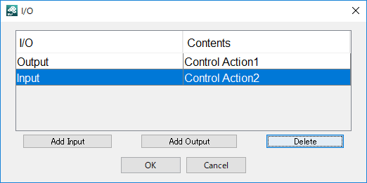
Double-click on a cell of the input/output in the Component Extracting Table to display the I/O dialog.
Select a row in the I/O dialog, and click on the [Delete] button.
This operation deletes the control action. The link and start/end points will not be deleted.
Double-click on the cell of the remarks to edit it.
Right-click on a blank column or row in the Component Extracting Table and click on [Generate Control Structure Diagram] on the context menu.
The Control Structure Diagram is generated with the contents of the Control Extracting Table. If the diagram exists, it opens.
The order of the components in the Component Extracting Table can be changed by dragging and dropping the row in the table.
To output the Component Extracting Table to an excel file, click on the [Output to the Excel File] button at top right on the Component Extracting Table.