This tutorial describes the STAMP/STPA procedures in STAMP Workbench based on the IPA First STAMP/STPA.
The STAMP/STPA procedures in STAMP Workbench are as follows:
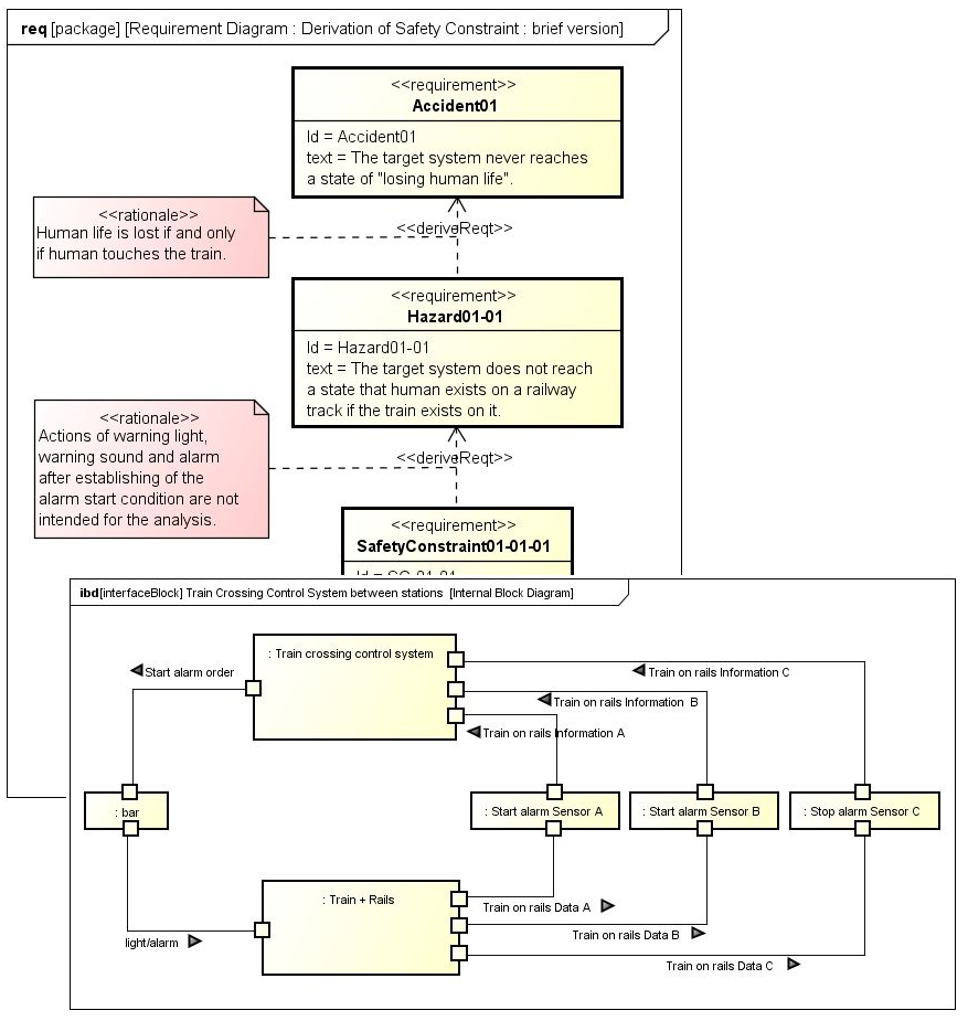
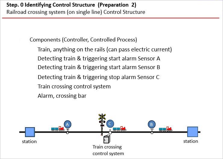
The system analyzes the target “Train Control System between stations on single line for the class1 or class 3 level crossing” of the IPA First STAMP/STPA Ver1.0 2016/3.
The STPA Procedure Preparations include the following procedures:
Launch STAMP Workbench, then create a project to control the STAMP/STPA analysis model.
To create a new project, select menu File ‣ New.
Hint
Instead of creating a new project, an analysis may be started by opening the project file offered by the organization and using it as a template.
Once the tool preparations are complete, understand the analysis target system.
Read the requirements specifications well to understand the analysis target system, draw a brief picture, or create a model pointing out the requirements, structures, and behaviors, using SysML or UML. Or read the results, including the model created by the engineering activities, and understand the analysis target system.
As there are varieties of methods to be used, the method is not directly supported in STAMP Workbench, but another tool may be used.
Once the analysis target system is understood, start the STAMP/STPA analysis, using STAMP Workbench.
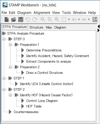
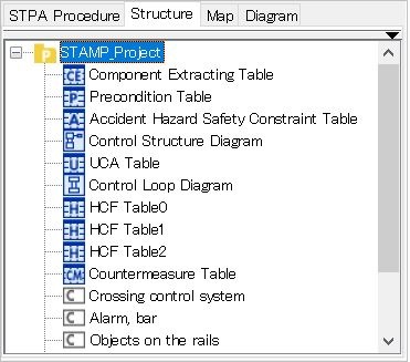
Refer to “STPA Procedure” displayed in the left pane of the tool. The STPA Procedure shows the STAMP/STPA procedures, using this tool. For anyone not accustomed to STPA, it is recommended to follow these procedures to learn the actual process.
Hint
The STPA Procedure is not mandatory. For the well-trained person it is possible to start drawing a Control Structure Diagram, using the diagram menu or structure tree without using the STPA Procedure view.
The structure tree is placed next to the STPA Procedure view. This exhaustively shows the diagrams and models created with the STPA Procedure view or diagram menu, in the tree view.
The STPA Procedure STEP 0 Preparation 1 includes the following procedures:
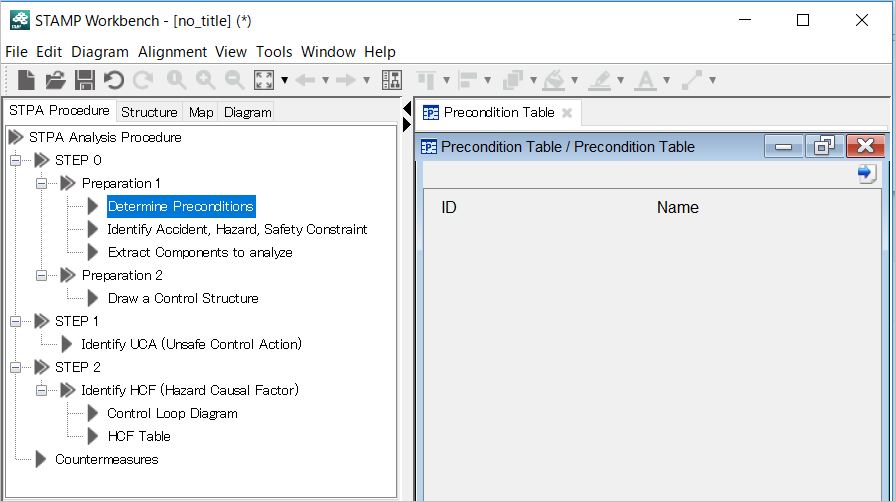
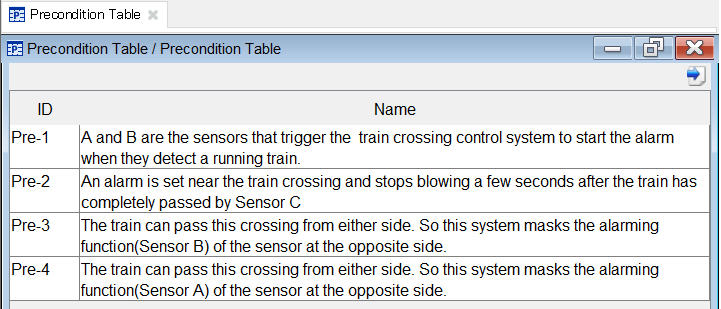
Once the analysis target system is understood, determine the process and preconditions of the system in the analysis range as a part of the work of clarifying it. This procedure is also described in “4.1 Determining Preconditions on page 13 of the First STAMP/STPA”.
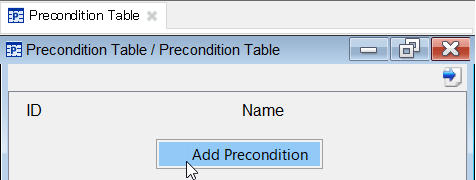
Right-click on a cell in the displayed table to select Add Precondition.
As a precondition is newly created and assigned a generated number, input “A and B are the sensors that trigger the train crossing control system to start the alarm when they detect a running train.“ in Name.
Let’s add other preconditions in the same way.
Understand the analysis target system, determine the suppositions/preconditions, then clarify for which accident the safety analysis is to be executed.
First, decide which accident is to be analyzed and extract the hazards, i.e., system conditions that lead to the accident. At the end, to avoid the accidents, extract the requirements or limitations for maintaining the safety of the analysis target as the safety constraints.
For the concepts and analysis procedures of the accidents, hazards and safety constraints, refer to “4.2 Step 0 Preparation 1 Identifying Accident, Hazard and Safety Constraints on page 15 in Section 2.2 on page 7 of the First STAMP/STPA”.
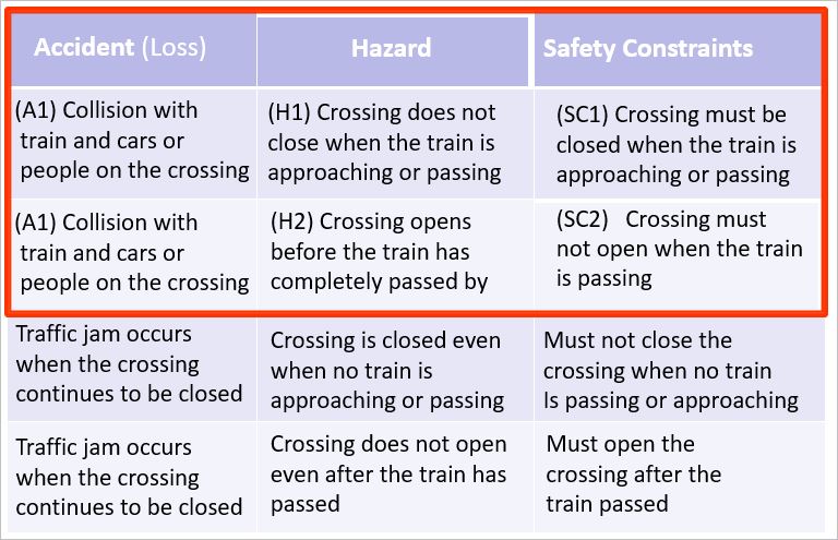
Create and control a model of the accidents, hazards and safety constraints and control them using the table in the same way as for the preconditions mentioned above. The following accidents, hazards and safety constraints described in the First STAMP/STPA with a series of operations are identified.
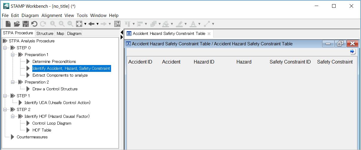
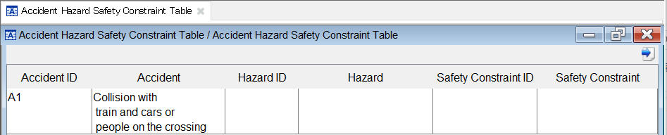
First, double-click STEP 0 ‣ Preparation 1 ‣ Identifying Accidents, Hazards, and Safety Constraints in the STPA procedure. Then the Accident Hazard Safety Constraint Table shown below will be displayed.
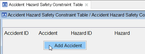
Right-click on a cell in the displayed table to select Add Accident.
As a new accident, in the same way as with the preconditions, is created and assigned a generated number, input “Collision with train and cars or people on the crossing”.
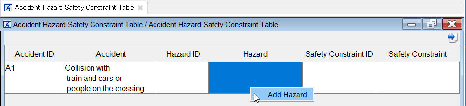
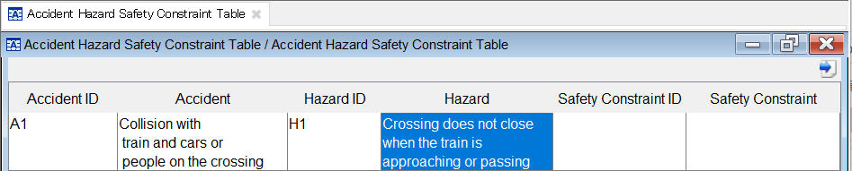
Next, to add the hazard that leads to this accident, right-click with a cell in the Hazard row selected to select Add Hazard.
This time set “Crossing does not close when the train is approaching or passing”.
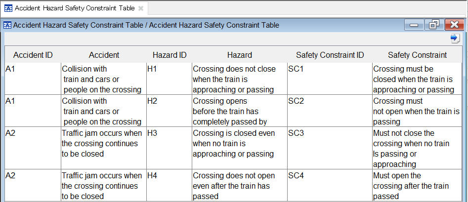
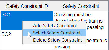
Next, to set the safety constraints, right-click with a cell in the Safety Constraints row selected to select Add Safety Constraint.
Set the accidents, hazards, and safety constraints described in the First STAMP/STPA with the same operations.
Hint
The hazard that leads to an accident may be the same as that analyzed with another accident. Or, the safety constraint may be extracted with the combination of another accident and hazard. In this case, the existing hazard or safety constraint can be selected with “Select Hazard” or “Select Safety Constraint”.
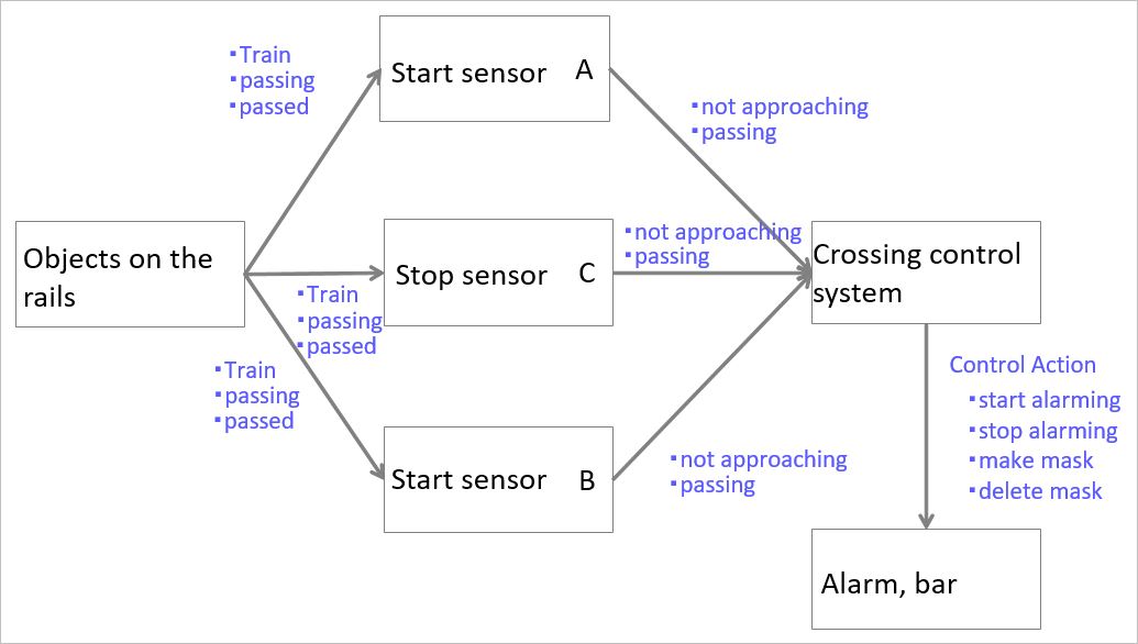
Identify the accidents, hazards and safety constraints, determine the target of analysis, then draw the structure and relationship of analysis target as a diagram or model.
In particular, components that represent the structure configuring the analysis target are drawn in the Control Structure Diagram and the relations among components are shown.
It may be difficult to determine what should be drawn on the control structure. In STAMP Workbench, for supporting creation of a control structure, components to be drawn can be determined using the Component Extracting Table, and according to the results, the control structure can be created.
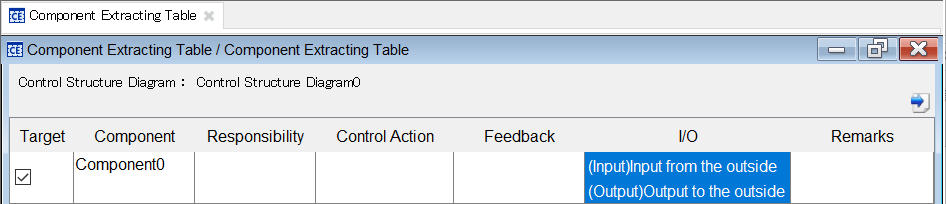
Then, double-click STEP 0 ‣ Preparation 1 ‣ Extract Components to Analyze in the STPA procedures to display the Component Extracting Table.
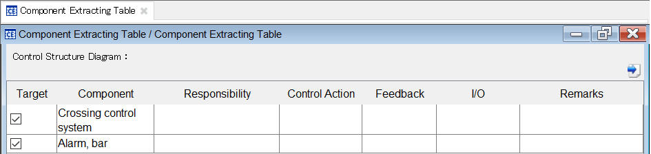
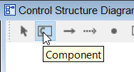
The Component Extracting Table is displayed. Right-click on a cell in the displayed table and select Add Component.
As a row for one component is added in the same manner as with the table mentioned above, add “Crossing Control System” and “Alarm, Bar” as components that may be drawn on the control structure.
Click on the cell to design the control action and feedback for this Crossing Control System for each cell.
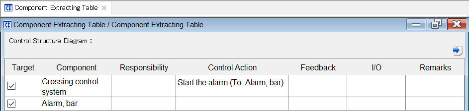
For example, to add the control action “Start the alarm” to “Alarm, Bar” from “Crossing Control System”, proceed as follows:
- Double-click on the cell of the control action of the Crossing Control System.
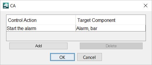
- The Control Action dialog is displayed. Click on the Add button.
- Select “Alarm, Bar” as the Target Component.
- Set “Start the alarm” in the Control Action.
- After setting the Control Action and Target Component, click on the OK button to finalize the edit.
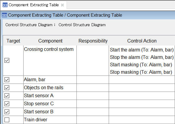
The results of this operation may become as follows:
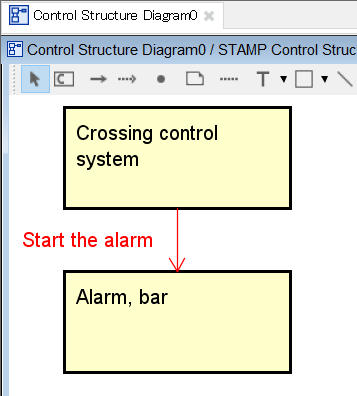
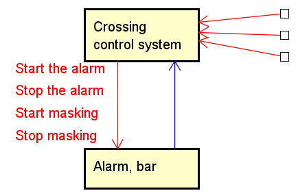
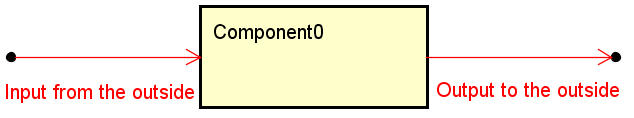
Right-click on the Component Extracting Table to select Generate Control Structure Diagram. Then the Control Structure Diagram shown below will be drawn from the models that have previously been designed.
Thus the components and their correlations are determined using the table, and the results will be drawn as the Control Structure Diagram.
Hint
This example First STAMP/STPA analyzes and concludes that a train driver is not included as a component.
The Component Extracting Table has “Target” to define the out-of-range parameters of the analysis target. To exclude the train driver from the analysis target, proceed as follows:
Hint
The relations between an analysis-target component and the outside world can be designed with “I/O” on the Component Extracting Table.
The STPA Procedure STEP 0 Preparation 2 includes the following procedures:
The Control Structure Diagram has already been created from the Component Extracting Table. In STAMP Workbench, the STPA procedures by IPA are not mandatory. It is possible to start drawing the STPA with the Control Structure Diagram.
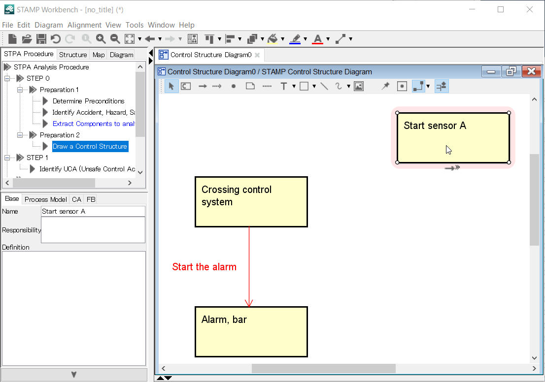
Now draw the control structure shown below that is described in “4.3 Step 0 Preparation 2 Draw the Control Structure” in the First STAMP/STPA in the Control Structure Diagram drawn from the Component Extracting Table.
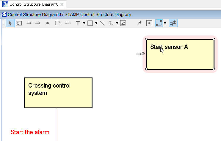
Input Start Sensor A in the created component directly.
Hint
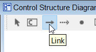
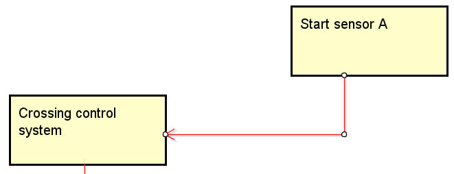
Using the draw suggest function on a diagram, a control structure can be described without moving the mouse repeatedly on the tool bar on the Link. Click on the line arrow symbol to select a component to be connected, and the link will be created.
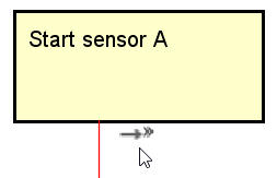
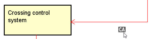
Clicking on the “>>” symbol of the line arrow enables you to select a link to define the control action or feedback.

Hint
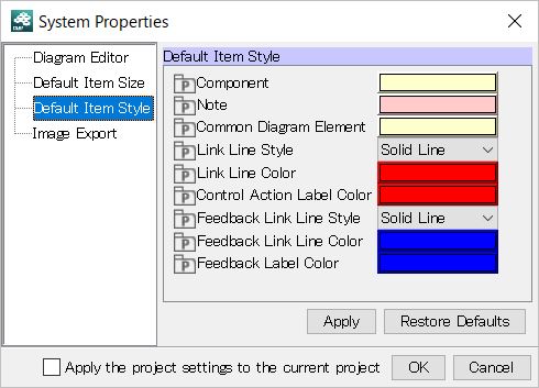
The link line colors of the control action and feedback have been set to red and blue, respectively, as default, as recommended by IPA.
This setting can be changed by selecting Tool ‣ System Properties ‣ Default Item Style ‣ Control Action/Feedback Line Color. Other than color, Line Type can be selected as Solid Line or Dashed Line.
The control structure is constructed by adding and editing the component, link, control action, and feedback.
The STPA Procedure STEP 1 includes the following procedures:
Once the structure of the analysis target is constructed as a control structure, it is analyzed using the UCA Table as to whether the control action can lead to the hazard/action from a viewpoint of a guide word for each control action.
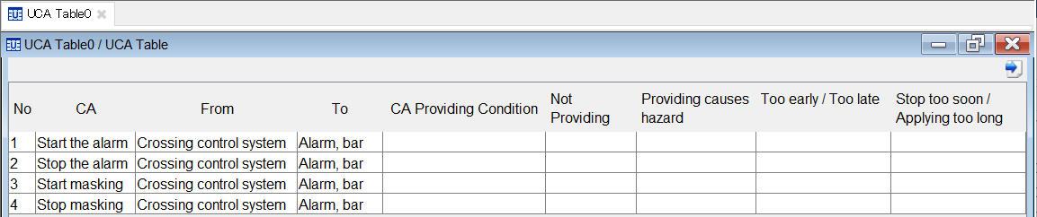
Then double-click STEP 1 ‣ Identify UCA (Unsafe Control Action) in the STPA procedure.
In the UCA Table, the control actions automatically extracted from the control structure are displayed. For each control action, analyze the viewpoint of the guide word, such as “Not Providing”.
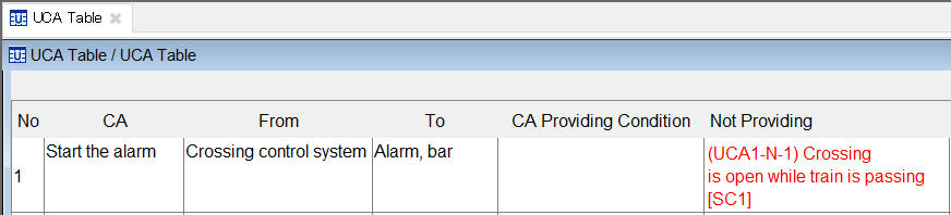
This time if the control action “Start the alarm” is set to Not Providing, input the analysis that the unsafe result of “The train passes the railroad crossing without ringing the alarm” is generated.
- First, double-click on the cell on which “Start the alarm” and “Not Providing” are crossed. The UCA dialog is displayed. Press “Add UCA”.
- As a UCA is added, input “Crossing is open while train is passing” in the Text.
- Double-click on a cell of “Violating Safety Constraint” to select the safety constraint designed with the accident, hazard and safety constraint table that the UCA violates.
- Finally click on the OK button.
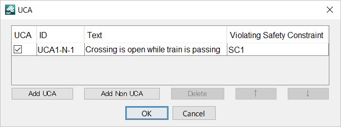
With these procedures, the UCA Table is as shown below.
The UCA will be analyzed with these operations.
Hint
To change the order of the control actions in the UCA Table, drag the line and drop it at the desired position.
The STPA Procedure STEP 2 includes the following procedures:
Once the UCA is extracted, identify the Hazard Causal Factor for each control action considered as the UCA.
As one of the methods, create a control structure that focuses on the control action considered as the UCA that is named in the Control Loop Diagram with the Control Structure Diagram.
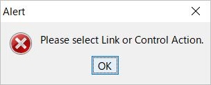
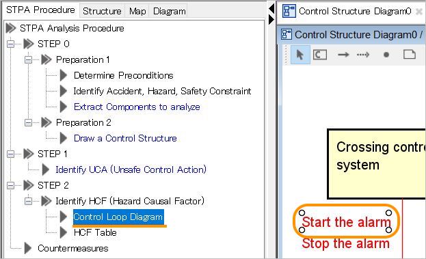
Then double-click STEP 2 ‣ HCF ‣ Control Loop Diagram in the STPA procedures. The alert dialog shown below will be displayed.
As described above, the Control Loop Diagram is created by focusing on a control action. So it is necessary to select the control action or link that is focused on in the Control Structure Diagram.
Then open the Control Structure Diagram and double-click on the Control Loop Diagram of the STPA procedures again with the control action “Start the alarm” selected.
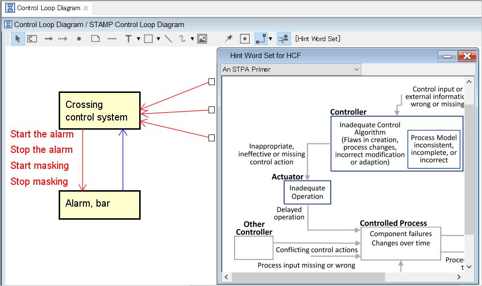
A Control Loop Diagram whose components other than those that are directly related to the selected control actions are omitted as the input/output from/to an external device as shown below, is created.
In the case of the First STAMP/SPTA, there is no control loop and the HCF analysis is executed with the control structure. However in this tutorial, analysis is executed using the control loop.
One of the HCF analysis methods in the Control Loop Diagram is to analyze the HCF by referring to hint words that may give the hint recommending discard and the control loop.
Click on Tool Bar ‣ Hint Word Set in the Control Loop Diagram.
Then the hint words are displayed, as shown below. While observing the Control Loop Diagram, execute the analysis of whether the causes to lead to a hazard occur or not in the status indicated by each hint word.
Hint
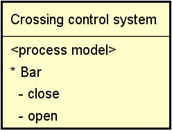
In the Control Loop Diagram (or Control Structure Diagram), the status of the target to be controlled that the controller recognizes can be designed as a process model.
In STAMP Workbench, select a component and right-click Process Model Compartment Visibility. The compartment in which the process model can be designed is displayed.
In the displayed process model compartment, the process variable and process value can be designed by right-clicking or in the property view.
Organize the HCF extracted with the procedures mentioned above in the HCF Table.
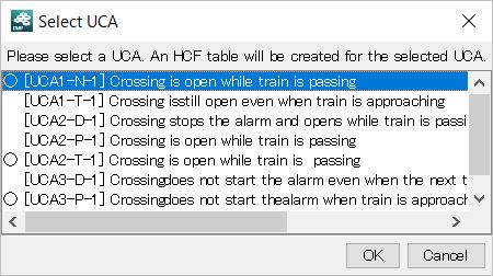
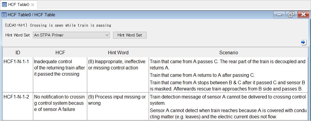
Double-click STEP 2 ‣ Identify HCF ‣ HCF Table in the STPA procedures.
Then the dialog to select the HCF for which the UCA to be organized is displayed. Select the UCA currently being analyzed in the Control Loop Diagram.
In this dialog, the circle symbol is added to the UCA that created the HCF Table, which enables you to identify the UCA for which the HCF analysis has not been executed.
When the HCF Table is displayed, add an HCF in the same way as in the operations before and create a scenario to lead to the HCF and design for the hint word from which it was extracted.
The STPA Procedure STEP 3 includes the following procedures:
The last STPA procedure is to consider the countermeasures for the extracted HCF.
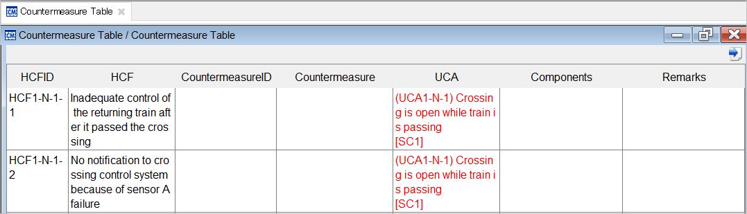
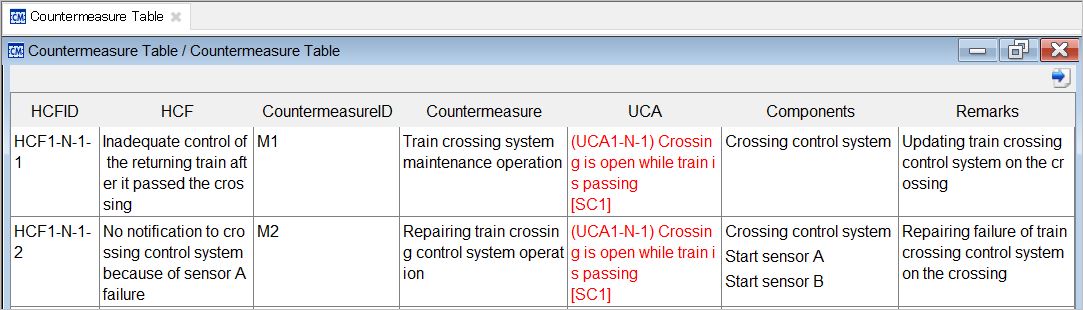
Double-click Countermeasures in the STPA procedure. Then the Countermeasure Table to design the countermeasures for the extracted HCF is displayed.
Right click on the countermeasures cell of this table and add the countermeasures using Add Countermeasure or set the Target Component by double-clicking on the cell of the Target Component.
These operations will finalize the countermeasures for the HCF.
In STPA, during the UCA analysis, an omission is found in the control structure, and frequently the procedures go back. Execute the STPA analysis with iterative analysis being done as described.