This chapter describes the Diagram Editor that is used to edit Diagrams.
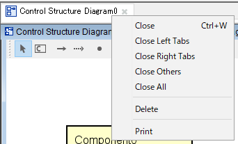
- Close
Close the selected diagram/table.
- Close Left Tabs, Close Right Tabs
Close all the Diagram Editors on the left or right side of the selected diagram/table.
- Close Others
Close all the Diagram Editors except the selected diagram/table.
- Close All
Close the all diagrams/tables.
- Delete
Delete the selected diagram/table.
Print the current diagram/table.
Draw Suggest Feature appears when you have a mouse over a Model Element in the diagram, providing with a set of suggested Model Elements to help you with modeling faster.
To switch On/Off the Draw Suggest Feature, click  [Suggest Feature] on the Tool palette.
While you hold [Shift] key down, setting is toggled another one.
The default setting can be done in the [Tool]-[System Properties]-[Diagram Editor]-[Enable Suggest Feature].
Note
Some elements (e.g. Link) are not added to the Structure Tree.
Double-click on the Diagram Editor to create a main Diagram Element of the Diagram.
Diagram Diagram Element Control Structure Diagram Component Control Loop Diagram Component
Double-click the name of the Diagram Element and edit the name.
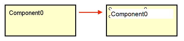
Or, edit the name in the [Structure Tree] or in the [Property View].
The size of the Diagram Element is automatically adjusted. For example, the name of the Component is edited to a longer name, the size is enlarged automatically.
To resize manually, click the target Diagram Element and drag the corner.
Note
Selecting all Diagram Elements in a Diagram
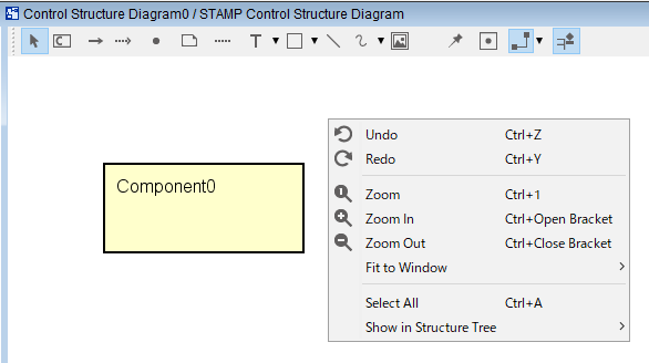
- To select all Model Elements in a Diagram, select [Edit] - [Select All] in the Main Menu, or right-click on the Diagram Editor and select [Select All] from the Context Menu.
- [Ctrl+A], the short cut key for [Select All] is also available.
To cancel a selection, hold down the [Shift] or [Ctrl] key and reselect the selected Diagram Elements.
Diagram Elements copied by [Copy to Clipboard] are stored in the Clipboard and can be pasted into other applications (MS Word, etc) as images or EMFs (Enhanced Meta File).
The Color Selection contains six image color groups: Aqua, Earth, Nature, Spring, Passion, and Winter.
[Favorite] can be used to store your favorite colors up to 10 colors.
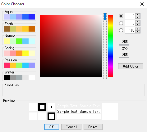
Diagram Element to set font color
- Component Name, Process Model Variable, Value
- Control Action
- Feedback
- Note
- Text
To edit the style of elements, use the Context menu.
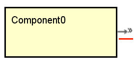
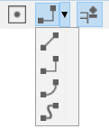
There are four line styles: Line, Line (Right Angle), Curve, Curve (Right Angle). By default, Line (Right Angle) is used for all diagrams.
To change the end point of a Line, simply drag the end point onto a new target.
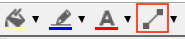
There are four line styles: Line, Line (Right Angle), Curve, Curve (Right Angle).
Right-click on the target Line in the Diagram Editor and select [Line style] - [Line]/[Line (Right Angle)]/[Curve]/[Curve (Right Angle)].
The line mode of the Diagram Editor can be selected in the Tool Pallet.
Note
- Existing Lines are not changed to the selected line mode.
Note
The Map in the Project View can be used to enlarge and shrink Diagrams.
Right-drag diagrams to move in the Diagram Editor.
Diagrams can be moved vertically by rotating the mouse wheel. When the mouse wheel is rotated forwards, Diagrams are moved upwards. When the mouse wheel is rotated backwards, Diagrams are moved downwards.
Diagrams can be moved horizontally by holding down the [Shift] key and rotating the mouse wheel. When the mouse wheel is rotated forwards, Diagrams are moved to the right. When the mouse wheel is rotated backwards, Diagrams are moved to the left.
Select the target Diagram Elements and click one of the following Align Buttons on the Tool Bar.
- Align Top
Align Diagram Elements with the top end of the highest Diagram Element.
- Align Horizontal Center
Align Diagram Elements along the midpoint between the highest and lowest Diagram Elements.
- Align Bottom
Align Diagram Elements with the bottom end of the lowest Diagram Element.
- Align Horizontal Even
Horizontally align Diagram Elements with even spacing.
- Adjust Height
Adjust the height of Diagram Elements to the highest Diagram Element.
- Align Left
Align Diagram Elements with the left side of the leftmost Diagram Element.
- Align Vertical Center
Align Diagram Elements along the midpoint between the leftmost and rightmost Diagram Elements.
- Align Right
Align Diagram Elements with the right side of the rightmost Diagram Element.
- Align Vertical Even
Vertically align Diagram Elements with even spacing between the highest and lowest Diagram Elements.
- Adjust Width
Adjust the width of Diagram Elements to the widest Diagram Element.
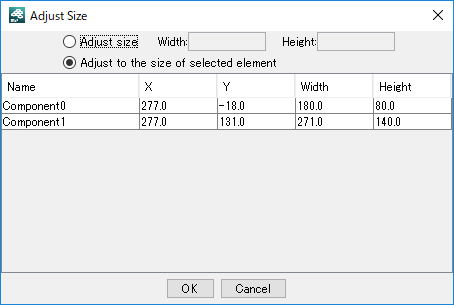
The size of the Diagram Elements can be adjusted to the selected Diagram Element or the specified width and height.
Some of the Diagram Elements may not be adjusted properly depending on the length of the name and so on.
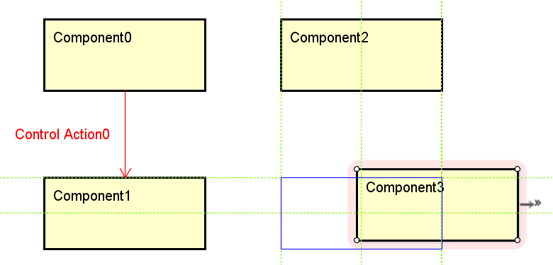
The Align Guide (green line) appears on the Diagram Editor when moving the Diagram Elements. This function helps to align the Diagram Elements to other Diagram Elements.
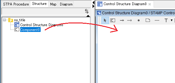
Jump to a Model in the Structure Tree from a Diagram Element.
Jump to a Diagram in the Structure Tree from the Diagram Editor.
[Bring to Front]
Move the selected Diagram Element to the top.
[Bring Forward]
Move the selected Diagram Element one step closer to the front.
[Send Backward]
Move the selected Diagram Element one step back.
[Send to Back]]
Send the selected Diagram Element to the back of all the Diagram Element.
- Using [Edit] - [Depth Arrangement] in the Main Menu
Select the Model Element in the Diagram Editor and select the way you would like to move it from [Edit]-[Depth Arrangement] in the Main Menu.
- Using on the Tool Bar
Select the
icon of the way you would like to move the selected Model Element on the Tool Bar.
- Using the Context Menu
- Right-click on the Model Element(s) you would like to move.
- Select the way you would like to move from the [Depth Arrangement] menu.