The window consists of Management View, Project View, Property View, and Diagram Editor.
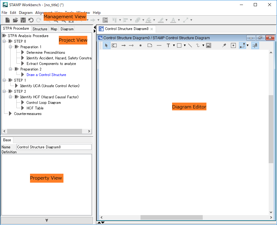
The Management View is used for the basic operations of STAMP Workbench . The Main Menu includes functions related to the whole Project, such as file operation and editing. Frequently used functions can also be found on the Tool Bar
The Project View provides an overview of the whole Project. Tabs at the top can be used to switch the Project View between STPA Procedure, Structure Tree, Map and Diagram.
STPA Procedure View displays the STPA analysis procedure in the tree format. The tree helps to create diagrams/tables and analyze STPA by following the step-by-step procedure. Diagrams/Tables can be created by double-clicking on each node of the tree.
The Structure Tree View displays Models in a tree structure. Various operations can be carried out by using the Context Menu of Model Elements.
The Map View provides an overview of the Diagram that is opened in the Diagram Editor. The area displayed in the Diagram Editor can be specified by a right-drag. The Diagram in the Diagram Editor can be scrolled using a left-drag. This function is especially useful for big Diagrams that do not fit in the screen. (Tables are not displayed.)
The Diagram View provides a list of all Diagrams and Tables included in the Project.
The Property View is used to display and edit the properties of Model Elements.
Select the target Model in the Structure Tree or in the Diagram Editor.
The Diagram Editor is used to edit Diagrams/Tables and Models. Multiple Diagrams/Tables can be opened in the Diagram Editor. Use Tabs on the top to switch between Diagrams/Tables.
Elements in Projects, such as Components or Control Actions, are called Model. Model is an element that exists in the project, in contrast, Diagram Element is a notation that represents the Model in diagrams. Each Diagram Element can have different color or size.